Engine coolant temperature: 0—45 °C {32—113 °F}, 60 °C {140 °F} or more
ac9uuw00007891
|
DTC P0171:00 [PCM (SKYACTIV-G 2.5T)]
id0102s8934200
Details On DTCs
|
DESCRIPTION |
Fuel trim system too lean |
|
|---|---|---|
|
DETECTION CONDITION
|
Determination conditions
|
• Any one of the following conditions is met:
|
|
Preconditions
|
• Engine coolant temperature: 0—45 °C {32—113 °F}, 60 °C {140 °F} or more*1
*1: Standard can be verified by displaying PIDs using M-MDS
|
|
|
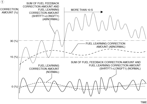
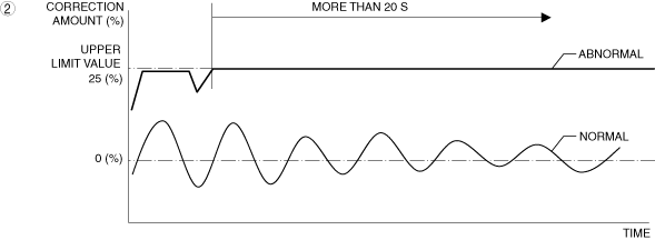
Malfunction determination period
|
• 10 s or 20 s period
|
|
|
Drive cycle
|
• 2
|
|
|
Self test type
|
• CMDTC self test
|
|
|
Sensor used
|
• A/F sensor
|
|
|
FAIL-SAFE FUNCTION
|
• Not applicable
|
|
|
VEHICLE STATUS WHEN DTCs ARE OUTPUT
|
• Illuminates check engine light.
|
|
|
POSSIBLE CAUSE
|
• Erratic signal to PCM
• High-pressure side fuel delivery system malfunction
• Fuel leakage in fuel line
• Low-pressure side fuel delivery system malfunction
• Fuel injector malfunction
• Improper operation of purge control system
• PCV valve malfunction
• MAF sensor malfunction
• Air cleaner element malfunction
• MAP sensor malfunction
• Air suction in intake air system
• Improper operation of electric variable valve timing control system
• Improper operation of hydraulic variable valve timing control system
• A/F sensor malfunction
• Poor fuel quality
• PCM malfunction
|
|
System Wiring Diagram
Function Explanation (DTC Detection Outline)
ac9uuw00007891
|
ac9uuw00007892
|
Repeatability Verification Procedure
PID Item/Simulation Item Used In Diagnosis
PID/DATA monitor item table
|
Item |
Definition |
Unit |
Condition/Specification |
|---|---|---|---|
|
APP
|
Accelerator pedal opening angle (relative value) with the fully released status as 0% and fully depressed status as 100%
|
%
|
• Accelerator pedal released: Approx. 0%
• Accelerator pedal fully depressed: Approx. 100%
|
|
ECT
|
Engine coolant temperature input from ECT sensor
|
°C, °F
|
• Displays ECT
|
|
ECT sensor voltage
|
V
|
Ignition switched ON (engine off)
• ECT is 29 °C {84 °F}: Approx. 2.65 V
Idle (after warm up)
• ECT is 88 °C {190 °F}: Approx. 0.71 V
|
|
|
EVAPCP
|
Purge solenoid valve control duty value
|
%
|
• Idle (after warm up): 0% (Engine coolant temperature 59 °C {140 °F} or less)
• Racing (Engine speed 2,000 rpm): 33—35% (ECT is 94 °C {201 °F})
• Racing (Engine speed 4,000 rpm): 53—55% (ECT is 94 °C {201 °F})
|
|
FP
|
Fuel pump relay operation status
|
Off/On
|
• Ignition switched ON (engine off): Off
• Cranking: On
• Idle (after warm up): On
|
|
FUEL_PRES
|
Fuel pressure input from high fuel pressure sensor
|
KPa {MPa}, mBar {Bar}, psi, in H20
|
• Displays fuel pressure
|
|
High fuel pressure sensor voltage
|
V
|
Ignition switched ON (engine off)
• Fuel pressure is approx. 16.91 MPa {172.4 kgf/cm2, 2453 psi}: Approx. 2.91 V
Idle (after warm up)
• Fuel pressure is 3.44—3.95 MPa {35.1—40.2 kgf/cm2, 499—572 psi}: 0.98—1.05 V (ECT is 90 °C {194 °F})
|
|
|
IAT2
|
Intake air temperature (No.2) input from IAT sensor No.2
|
°C, °F
|
• Displays IAT (No.2)
|
|
IAT sensor No.2 voltage
|
V
|
• IAT2 is 20 °C {68 °F}: Approx. 3.57 V
• IAT2 is 40 °C {104 °F}: Approx. 2.70 V
• IAT2 is 60 °C {140 °F}: Approx. 1.87 V
|
|
|
MAF
|
Mass air flow input from MAF sensor
|
g/Sec
|
• Displays MAF
|
|
MAF sensor voltage
|
V
|
• Ignition switched ON (engine off) (MAF: 0.59 g/s {0.078 lb/min}): Approx. 0.72 V
• Idle (after warm up) (MAF: 2.17 g/s {0.287 lb/min}): Approx. 0.97 V
• Racing (engine speed is 2,000 rpm) (MAF: 4.73 g/s {0.626 lb/min}): Approx. 1.26 V
|
|
|
MAP
|
Manifold absolute pressure input from MAP sensor
|
KPa {MPa}, mBar {Bar}, psi, in H20
|
• Displays MAP
|
|
MAP_V
|
MAP sensor voltage
|
V
|
• Ignition switched ON (engine off) (no load) (MAP: 102 kPa {1.04 kgf/cm2, 14.8 psi}): Approx. 1.75 V
• Idle (after warm up) (no load) (MAP: 30 kPa {0.31 kgf/cm2, 4.4 psi}): Approx. 0.68 V
• Racing (engine speed is 2,000 rpm) (no load) (MAP: 27 kPa {0.28 kgf/cm2, 3.9 psi}): Approx. 0.61 V
|
|
O2S11
|
A/F sensor current
|
µA
|
• Idle (after warm up): 0—50 µA
• Deceleration fuel cut (accelerator pedal released from engine speed of 4,000 rpm or more): Approx. 3.84 mA
|
|
TP_REL
|
Throttle valve opening angle (relative value) with value at throttle valve fully close timing as the start point
|
%
|
• Accelerator pedal released: Approx. 12%
• Accelerator pedal fully depressed: Approx. 82%
|
|
VT_EX_ACT
|
Actual exhaust variable valve timing control
• Retard amount from max advance position
|
° (deg)
|
• Displays actual exhaust variable valve timing—retard amount from max advance position
|
|
VT_EX_DES
|
Target exhaust variable valve timing control
• Retard amount from max advance position
|
° (deg)
|
• Displays target exhaust variable valve timing—retard amount from max advance position
|
|
VT_IN_ACT
|
Actual intake variable valve timing control
• Advance amount from max retard position
|
° (deg)
|
• Displays actual intake variable valve timing—advance amount from max retard position
Idle (after warm up)
Racing (engine speed is 2,000 rpm)
|
|
VT_IN_DES
|
Target intake variable valve timing control
• Advance amount from max retard position
|
° (deg)
|
• Displays target intake variable valve timing—advance amount from max retard position
Idle (after warm up)
Racing (engine speed is 2,000 rpm)
|
Simulation item table
|
Item |
Applicable component |
Unit/Condition |
Engine condition |
Other condition |
|---|---|---|---|---|
|
INJ_1
|
Fuel injector No.1
|
OFF
|
• Under the following conditions:
|
|
|
INJ_2
|
Fuel injector No.2
|
OFF
|
• Under the following conditions:
|
|
|
INJ_3
|
Fuel injector No.3
|
OFF
|
• Under the following conditions:
|
|
|
INJ_4
|
Fuel injector No.4
|
OFF
|
• Under the following conditions:
|
Function Inspection Using M-MDS
|
STEP |
INSPECTION |
RESULTS |
ACTION |
|---|---|---|---|
|
1
|
PURPOSE: VERIFY RELATED SERVICE INFORMATION AVAILABILITY
• Verify related Service Information availability.
• Is any related Service Information available?
|
Yes
|
Perform repair or diagnosis according to the available Service Information.
• If the vehicle is not repaired, go to the next step.
|
|
No
|
Go to the next step.
|
||
|
2
|
PURPOSE: IDENTIFY TRIGGER DTC FOR FREEZE FRAME DATA
• Is the DTC P0171:00 on FREEZE FRAME DATA?
|
Yes
|
Go to the next step.
|
|
No
|
Go to the troubleshooting procedure for DTC on FREEZE FRAME DATA.
|
||
|
3
|
PURPOSE: RECORD VEHICLE STATUS AT TIME OF DTC DETECTION TO UTILIZE WITH REPEATABILITY VERIFICATION
• Record the FREEZE FRAME DATA/snapshot data on the repair order.
|
—
|
Go to the next step.
|
|
4
|
PURPOSE: VERIFY IF INPUT SIGNAL TO PCM AFFECTS FUEL INJECTION
• Start the engine.
• Access the following PIDs using the M-MDS:
• Is there any signal that is far out of specification?
|
Yes
|
Inspect the suspected sensor and related wiring harness.
• If there is any malfunction:
• If there is no malfunction:
|
|
No
|
Go to the next step.
|
||
|
5
|
PURPOSE: VERIFY CONNECTOR CONNECTIONS
• Start the engine.
• Access the following PIDs using the M-MDS:
• When the following parts are shaken, does the PID value include a PID item which has changed?
|
Yes
|
Repair or replace the applicable connector parts.
Go to the troubleshooting procedure to perform the procedure from Step 20.
|
|
No
|
Go to the next step.
|
||
|
6
|
PURPOSE: VERIFY FUEL PRESSURE (HIGH-SIDE) MALFUNCTION
• Switch the ignition off.
• Reconnect all disconnected connectors.
• Start the engine and idle it.
• Access the FUEL_PRES PID using the M-MDS.
• Is the FUEL_PRES PID value approx. 3 MPa {31 kgf/cm2, 435 psi}?
|
Yes
|
Go to the next step.
|
|
No
|
FUEL_PRES PID value is lower than 3 MPa {31 kgf/cm2, 435 psi}:
• Go to the troubleshooting procedure to perform the procedure from Step 1.
FUEL_PRES PID value is higher than 3 MPa {31 kgf/cm2, 435 psi}:
• Go to Step 8.
|
||
|
7
|
PURPOSE: VERIFY FUEL PRESSURE (LOW-SIDE) MALFUNCTION
• Bleed the remaining pressure in the fuel line using the following procedure.
• Switch the ignition off.
• Install the fuel pump relay.
• Switch the ignition ON (engine off).
• Display PID FUEL_PRES and simulation item FP using the M-MDS.
• Turn simulation item FP on.
• Is the FUEL_PRES PID value 550 kPa {5.61 kgf/cm2, 79.8 psi} or more?
|
Yes
|
Go to the next step.
|
|
No
|
Go to the troubleshooting procedure to perform the procedure from Step 5.
|
||
|
8
|
PURPOSE: VERIFY IF MALFUNCTION CAUSED BY FUEL INJECTOR IMPROPER OPERATION
• Switch the ignition off.
• Reconnect all disconnected connectors.
• Start the engine and idle it.
• Access the following simulation items using the M-MDS:
• Turn each fuel injector from on to off using the simulation items.
• Does the vibration during idling worsen?
|
Yes
|
Go to the next step.
|
|
No
|
Go to the troubleshooting procedure to perform the procedure from Step 7.
|
||
|
9
|
PURPOSE: VERIFY IF MALFUNCTION CAUSED BY PURGE SOLENOID VALVE IMPROPER OPERATION
• Start the engine and idle it.
• Access the EVAPCP PID using the M-MDS.
• Is the EVAPCP PID value normal?
|
Yes
|
Go to the next step.
|
|
No
|
Go to the troubleshooting procedure to perform the procedure from Step 8.
|
||
|
10
|
PURPOSE: VERIFY MAF SENSOR
• Start the engine and idle it.
• Access the MAF PID using the M-MDS.
• Is the MAF PID value normal?
|
Yes
|
Go to the next step.
|
|
No
|
Go to the troubleshooting procedure to perform the procedure from Step 10.
|
||
|
11
|
PURPOSE: VERIFY MAP SENSOR
• Start the engine and idle it.
• Access the following PIDs using the M-MDS:
• Are all items normal?
|
Yes
|
Go to the next step.
|
|
No
|
Go to the troubleshooting procedure to perform the procedure from Step 12.
|
||
|
12
|
PURPOSE: VERIFY INTAKE VALVE TIMING
• Start the engine and idle it.
• Access the following PIDs using the M-MDS:
• Depress the accelerator pedal to increase the engine speed.
• Does the monitor value of the PID item VT_IN_ACT conform to the VT_IN_DES PID value?
|
Yes
|
Go to the next step.
|
|
No
|
Go to the troubleshooting procedure to perform the procedure from Step 14.
|
||
|
13
|
PURPOSE: VERIFY EXHAUST VALVE TIMING
• Start the engine and idle it.
• Access the following PIDs using the M-MDS:
• Perform the following:
• Does the monitor value of the PID item VT_EX_ACT conform to the VT_EX_DES PID value?
|
Yes
|
Go to the next step.
|
|
No
|
Go to the troubleshooting procedure to perform the procedure from Step 17.
|
||
|
14
|
PURPOSE: VERIFY A/F SENSOR
• Access the O2S11 PID using the M-MDS.
• Is the O2S11 PID value normal?
|
Yes
|
Go to the next step.
|
|
No
|
Go to the troubleshooting procedure to perform the procedure from Step 18.
|
||
|
15
|
PURPOSE: VERIFY DTC
• Switch the ignition off, then ON (engine off).
• Retrieve the PCM DTCs using the M-MDS.
• Are any DTCs present?
|
Yes
|
Go to the applicable DTC inspection.
Go to the troubleshooting procedure to perform the procedure from Step 1.
|
|
No
|
Go to the troubleshooting procedure to perform the procedure from Step 1.
|
Troubleshooting Diagnostic Procedure
|
STEP |
INSPECTION |
RESULTS |
ACTION |
|---|---|---|---|
|
1
|
PURPOSE: VERIFY IF CAUSE OF MALFUNCTION IS RELATED TO LACK OF FUEL
• Verify the remaining amount of fuel.
• Is there a lack of fuel?
|
Yes
|
Refill the fuel, then go to Step 20.
|
|
No
|
Go to the next step.
|
||
|
2
|
PURPOSE: DETERMINE INTEGRITY OF HIGH FUEL PRESSURE SENSOR
• Inspect the high fuel pressure sensor.
• Is there any malfunction?
|
Yes
|
Replace the fuel distributor, then go to Step 20.
|
|
No
|
Go to the next step.
|
||
|
3
|
PURPOSE: DETERMINE INTEGRITY OF HIGH PRESSURE FUEL PUMP
• Inspect the high pressure fuel pump.
• Is there any malfunction?
|
Yes
|
Replace the high pressure fuel pump, then go to Step 20.
|
|
No
|
Go to the next step.
|
||
|
4
|
PURPOSE: VERIFY IF MALFUNCTION RELATED TO FUEL LEAK FROM FUEL SYSTEM OR RESTRICTION AFFECTS DIAGNOSTIC RESULTS
• Inspect the fuel system pipes (low to high pressure sides) for fuel leakage and restriction.
• Is there any malfunction?
|
Yes
|
Repair or replace the malfunctioning part according to the inspection results, then go to Step 20.
|
|
No
|
Go to the next step.
|
||
|
5
|
PURPOSE: DETERMINE INTEGRITY OF FUEL PUMP CONTROL MODULE
• Inspect the fuel pump control module.
• Is there any malfunction?
|
Yes
|
Replace the fuel pump control module, then go to Step 20.
|
|
No
|
Go to the next step.
|
||
|
6
|
PURPOSE: DETERMINE INTEGRITY OF FUEL PUMP UNIT
• Inspect the fuel pump unit.
• Is there any malfunction?
|
Yes
|
Replace the fuel pump unit, then go to Step 20.
|
|
No
|
Go to the next step.
|
||
|
7
|
PURPOSE: DETERMINE INTEGRITY OF FUEL INJECTOR
• Inspect the fuel injector.
• Is there any malfunction?
|
Yes
|
Replace the fuel injector, then go to Step 20.
|
|
No
|
Go to the next step.
|
||
|
8
|
PURPOSE: DETERMINE INTEGRITY OF PURGE SOLENOID VALVE
• Inspect the purge solenoid valve.
• Is there any malfunction?
|
Yes
|
Replace the purge solenoid valve, then go to Step 20.
|
|
No
|
Go to the next step.
|
||
|
9
|
PURPOSE: DETERMINE INTEGRITY OF PCV VALVE
• Inspect the PCV valve.
• Is there any malfunction?
|
Yes
|
Replace the PCV valve, then go to Step 20.
|
|
No
|
Go to the next step.
|
||
|
10
|
PURPOSE: DETERMINE INTEGRITY OF MAF SENSOR
• Inspect the MAF sensor.
• Is there any malfunction?
|
Yes
|
Replace the MAF sensor/IAT sensor No.1, then go to Step 20.
|
|
No
|
Go to the next step.
|
||
|
11
|
PURPOSE: VERIFY IF MALFUNCTION RELATED TO AIR CLEANER ELEMENT AFFECTS MEASUREMENT OF INTAKE AIR AMOUNT
• Inspect the air cleaner element.
• Is there any malfunction?
|
Yes
|
Replace the air cleaner element, then go to Step 20.
|
|
No
|
Go to the next step.
|
||
|
12
|
PURPOSE: DETERMINE INTEGRITY OF MAP SENSOR
• Reconnect all disconnected connectors.
• Inspect the MAP sensor.
• Is there any malfunction?
|
Yes
|
Replace the MAP sensor/IAT sensor No.2, then go to Step 20.
|
|
No
|
Go to the next step.
|
||
|
13
|
PURPOSE: VERIFY IF MALFUNCTION RELATED TO INTAKE AIR SYSTEM AFFECTS DIAGNOSTIC RESULTS
• Visually inspect for loose, cracked or damaged hoses on intake air system.
• Is there any malfunction?
|
Yes
|
Repair or replace the malfunctioning part according to the inspection results, then go to Step 20.
|
|
No
|
Go to the next step.
|
||
|
14
|
PURPOSE: DETERMINE INTEGRITY OF ELECTRIC VARIABLE VALVE TIMING DRIVER
• Inspect the electric variable valve timing driver.
• Is there any malfunction?
|
Yes
|
Replace the electric variable valve timing motor/driver, then go to Step 20.
|
|
No
|
Go to the next step.
|
||
|
15
|
PURPOSE: DETERMINE INTEGRITY OF ELECTRIC VARIABLE VALVE TIMING MOTOR
• Inspect the electric variable valve timing motor.
• Is there any malfunction?
|
Yes
|
Replace the electric variable valve timing motor/driver, then go to Step 20.
|
|
No
|
Go to the next step.
|
||
|
16
|
PURPOSE: DETERMINE INTEGRITY OF ELECTRIC VARIABLE VALVE TIMING ACTUATOR
• Inspect the electric variable valve timing actuator.
• Is there any malfunction?
|
Yes
|
Replace the electric variable valve timing actuator, then go to Step 20.
|
|
No
|
Go to the next step.
|
||
|
17
|
PURPOSE: DETERMINE INTEGRITY OF OCV
• Inspect the OCV.
• Is there any malfunction?
|
Yes
|
Replace the OCV, then go to Step 20.
|
|
No
|
Go to the next step.
|
||
|
18
|
PURPOSE: DETERMINE INTEGRITY OF A/F SENSOR
• Inspect the A/F sensor.
• Is there any malfunction?
|
Yes
|
Replace the A/F sensor, then go to Step 20.
|
|
No
|
Go to the next step.
|
||
|
19
|
PURPOSE: VERIFY IF MALFUNCTION RELATED TO EMISSION SYSTEM AFFECTS HO2S SIGNAL
• Verify the exhaust gas leakage from the exhaust system. (between A/F sensor and HO2S)
• Is there any malfunction?
|
Yes
|
Repair or replace the malfunctioning part according to the inspection results, then go to the next step.
|
|
No
|
Go to the next step.
|
||
|
20
|
PURPOSE: VERIFICATION OF VEHICLE REPAIR COMPLETION
• Always reconnect all disconnected connectors.
• Clear the DTC from the PCM memory using the M-MDS.
• Implement the repeatability verification procedure.
• Perform the Pending Trouble Code Access Procedure.
• Is the PENDING CODE for this DTC present?
|
Yes
|
Repeat the inspection from Step 1.
• If the malfunction recurs, replace the PCM.
|
|
No
|
DTC troubleshooting completed.
|