 |
ac9wzw00003836
ENGINE REMOVAL/INSTALLATION [SKYACTIV-G 2.5T]
id0110q8800400
1. Disconnect the negative battery terminal. (See NEGATIVE BATTERY TERMINAL DISCONNECTION/CONNECTION.)
2. Remove the front under cover No.1 and No.2. (See FRONT UNDER COVER No.1 REMOVAL/INSTALLATION.) (See FRONT UNDER COVER No.2 REMOVAL/INSTALLATION.)
3. Remove the front splash shield. (See FRONT SPLASH SHIELD REMOVAL/INSTALLATION.)
4. Drain the engine coolant. (See ENGINE COOLANT REPLACEMENT [SKYACTIV-G 2.5T].)
5. Drain the ATF. (See AUTOMATIC TRANSAXLE FLUID (ATF) REPLACEMENT [GW6A-EL, GW6AX-EL].)
6. Drain the transfer oil. (4WD) (See TRANSFER OIL REPLACEMENT [GW6AX-EL].)
7. Remove the front wheels and tires. (See WHEEL AND TIRE REMOVAL/INSTALLATION.)
8. Remove the plug hole plate. (See PLUG HOLE PLATE REMOVAL/INSTALLATION [SKYACTIV-G 2.5T].)
9. Remove the air cleaner, air hose and fresh air duct as a single unit. (See INTAKE-AIR SYSTEM REMOVAL/INSTALLATION [SKYACTIV-G 2.5T].)
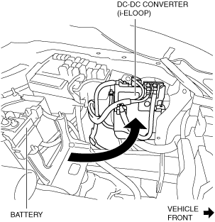
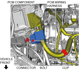
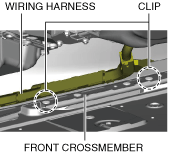
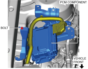
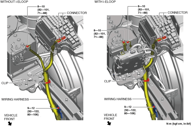
10. Remove the bolt, nut, clip and connector shown in the figure, and set the wiring harness aside.
ac9wzw00003836
|
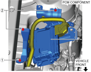
11. Set the DC-DC converter (i-ELOOP) aside in the direction of the arrow shown in the figure with the wiring harness connected. (with i-ELOOP) (See DC-DC CONVERTER (i-ELOOP) REMOVAL/INSTALLATION [i-ELOOP].)
ac9wzw00003837
|
12. Remove the battery and battery tray. (See BATTERY REMOVAL/INSTALLATION.)
13. Remove the air inlet pipe. (See INTAKE-AIR SYSTEM REMOVAL/INSTALLATION [SKYACTIV-G 2.5T].)
14. Remove the turbocharger air outlet pipe and charge air cooler inlet hose. (See INTAKE-AIR SYSTEM REMOVAL/INSTALLATION [SKYACTIV-G 2.5T].)
15. Remove the charge air cooler outlet pipe and charge air cooler outlet hose as a single unit. (See INTAKE-AIR SYSTEM REMOVAL/INSTALLATION [SKYACTIV-G 2.5T].)
16. Disconnect the selector cable. (See AUTOMATIC TRANSAXLE SHIFT MECHANISM REMOVAL/INSTALLATION.)
17. Disconnect the brake vacuum hose. (See VACUUM HOSE REMOVAL/INSTALLATION [L.H.D.].) (See VACUUM HOSE REMOVAL/INSTALLATION [R.H.D.].)
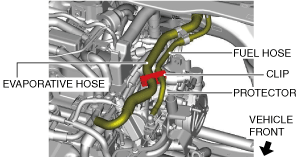
18. Disconnect the clip shown in the figure from the protector.
ac9wzw00004457
|
19. Disconnect the evaporative hose. (See PURGE SOLENOID VALVE REMOVAL/INSTALLATION [SKYACTIV-G 2.5T].)
20. Disconnect the fuel hose. (See QUICK RELEASE CONNECTOR REMOVAL/INSTALLATION [SKYACTIV-G 2.5T].)
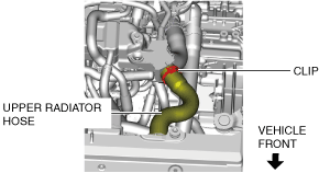
21. Disconnect the upper radiator hose.
ac9uuw00006344
|
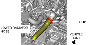
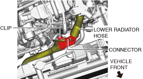
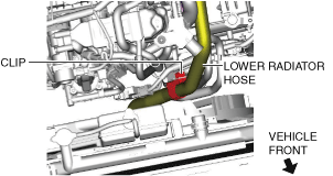
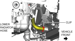
22. Remove the lower radiator hose and pipe component using the following procedure:
ac9uuw00006345
|
ac9wzw00005706
|
ac9uuw00007431
|
ac9uuw00006348
|
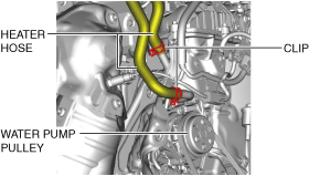
23. Disconnect the heater hoses.
ac9uuw00006349
|
24. Remove the generator drive belt. (See DRIVE BELT REMOVAL/INSTALLATION [SKYACTIV-G 2.5T].)
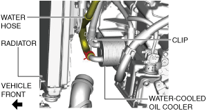
25. Disconnect the water hose from water-cooled oil cooler.
ac9uuw00006350
|
26. Disconnect the oil hoses from radiator. (if equipped) (See OIL COOLER REMOVAL/INSTALLATION [GW6A-EL, GW6AX-EL].)
27. Remove the A/C compressor with the cooler hose still connected and secure it using wire or rope so that it is out of the way. (See A/C COMPRESSOR REMOVAL/INSTALLATION.)
28. Remove the TWC installation nuts (WU-TWC side) and secure the TWC using wire or rope so that it is out of the way (2WD). (See EXHAUST SYSTEM REMOVAL/INSTALLATION [SKYACTIV-G 2.5T].)
29. Remove the TWC. (4WD) (See EXHAUST SYSTEM REMOVAL/INSTALLATION [SKYACTIV-G 2.5T].)
30. Remove the propeller shaft. (4WD) (See PROPELLER SHAFT REMOVAL/INSTALLATION.)
31. Disconnect the front drive shaft (LH) from the transaxle side and set the drive shaft (LH) out of the way. (See FRONT DRIVE SHAFT REMOVAL/INSTALLATION.)
32. Disconnect the front drive shaft (RH) from the transaxle side and set the drive shaft (RH) out of the way. (2WD) (See FRONT DRIVE SHAFT REMOVAL/INSTALLATION.)
33. Remove the front drive shaft (RH). (4WD) (See FRONT DRIVE SHAFT REMOVAL/INSTALLATION.)
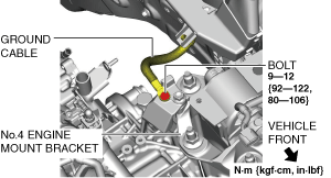
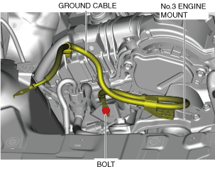
34. Remove the bolt and set the ground cable aside.
ac9uuw00006352
|
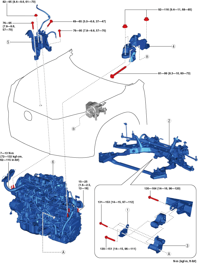
35. Remove in the order indicated in the table.
2WD
ac9uuw00006353
|
|
1
|
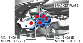
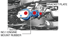
Bracket plate
|
|
2
|
No.1 engine mount rubber, front crossmember component
|
|
3
|
No.1 engine mount bracket
|
|
4
|
No.4 engine mount bracket
|
|
5
|
No.3 engine mount
|
|
6
|
Engine, transaxle
|
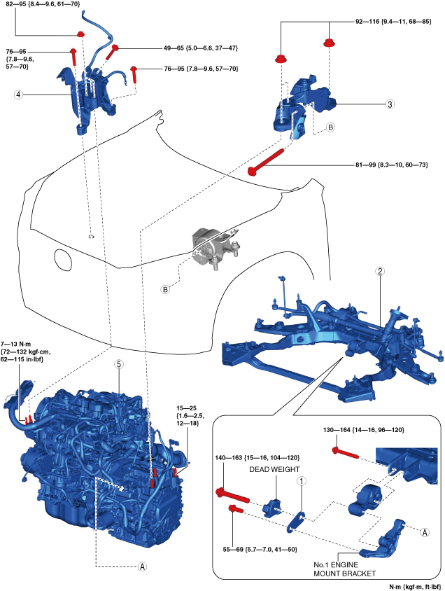
4WD
ac9uuw00006354
|
|
1
|
Bracket plate
|
|
2
|
No.1 engine mount rubber, front crossmember component
|
|
3
|
No.4 engine mount bracket
|
|
4
|
No.3 engine mount
|
|
5
|
Engine, transaxle
|
36. Install in the reverse order of removal.
37. Refill the transfer oil. (4WD) (See TRANSFER OIL REPLACEMENT [GW6AX-EL].)
38. Refill the ATF. (See AUTOMATIC TRANSAXLE FLUID (ATF) REPLACEMENT [GW6A-EL, GW6AX-EL].)
39. Refill the engine coolant. (See ENGINE COOLANT REPLACEMENT [SKYACTIV-G 2.5T].)
40. Start the engine, and inspect and adjust the following:
No.1 Engine Mount Rubber, Front Crossmember Component Removal Note
1. Disconnect the service plug. (with i-ELOOP) (See SERVICE PLUG DISCONNECTION/CONNECTION [i-ELOOP].)
2. Disconnect the generator terminal B cable. (with i-ELOOP) (See GENERATOR REMOVAL/INSTALLATION [WITH i-ELOOP (SKYACTIV-G 2.5T)].)
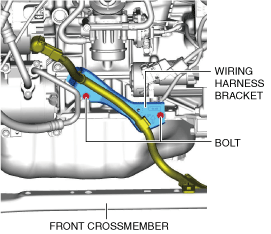
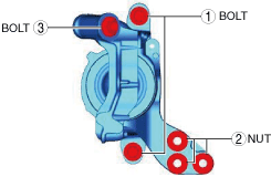
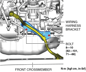
3. Remove the bolts shown in the figure and remove the wiring harness bracket. (with i-ELOOP)
ac9wzw00003838
|
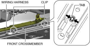
4. Remove the clips shown in the figure and set the wiring harness aside. (with i-ELOOP)
ac9wzw00003839
|
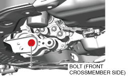
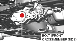
5. Loosen the No.1 engine mount rubber installation bolt (front crossmember side) shown in the figure.
2WD
ac9uuw00006355
|
4WD
ac9uuw00006356
|
6. Remove the No.1 engine mount rubber and the front crossmember component as a single unit. (See FRONT CROSSMEMBER REMOVAL/INSTALLATION.)
No.3 Engine Mount, No.4 Engine Mount Bracket Removal Note
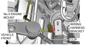
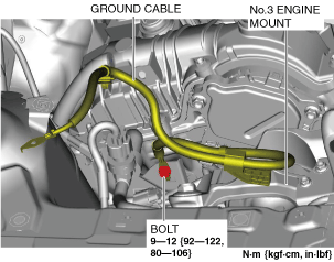
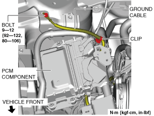
1. Remove the clip and bolt shown in the figure and set the ground cable aside.
ac9uuw00006357
|
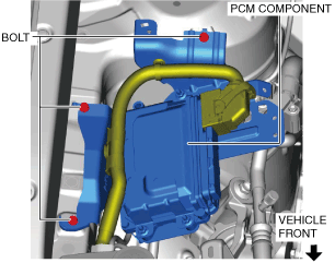
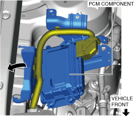
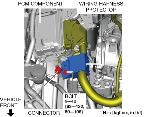
2. Set the PCM wiring harness and PCM component aside using the following procedure:
ac9wzw00005518
|
ac9uuw00006359
|
ac9uuw00006360
|
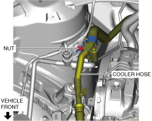
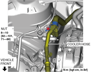
3. Remove the nut shown in the figure and set the cooler hose aside.
ac9wzw00005519
|
4. Disconnect the ground cable shown in the figure.
ac9uuw00006362
|
5. Disconnect the clip shown in the figure.
ac9uuw00006363
|
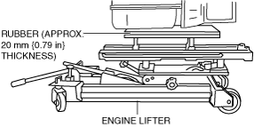
6. Secure the engine and transaxle using a commercially available engine lifter.
ac9wzw00005707
|
7. Remove the No.4 engine mount bracket.
8. Remove the No.3 engine mount.
Engine Mount Installation Note
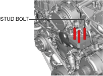
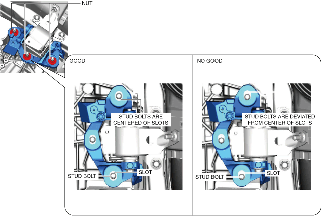
1. Tighten the engine front cover stud bolts.
ac9uuw00006364
|
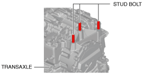
2. Tighten the transaxle stud bolts.
ac3wzw00000647
|
3. Secure the engine and transaxle using a commercially available engine lifter.
ac9wzw00005707
|
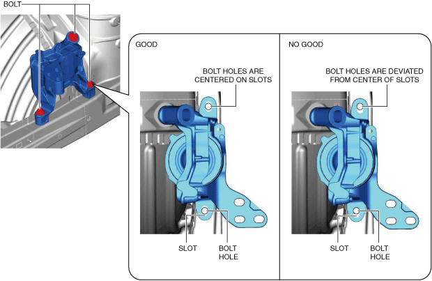
4. Temporarily tighten the No.3 engine mount installation bolts and nuts using the following procedure:
ac9uuw00006365
|
ac9uuw00006366
|
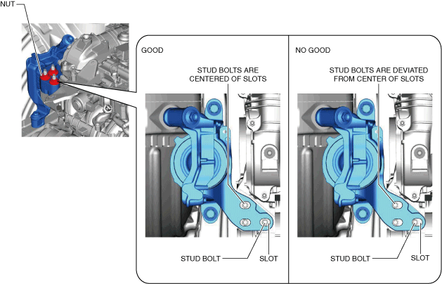
5. Temporarily tighten the No.4 engine mount bracket installation bolt and nuts using the following procedure:
ac9uuw00006367
|
ac9uuw00006368
|
6. Install the No.1 engine mount rubber and the front crossmember component as a single unit. (See FRONT CROSSMEMBER REMOVAL/INSTALLATION.)
7. Temporarily tighten the following parts:
ac9uuw00006369
|
ac9uuw00006370
|
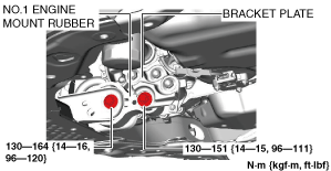
8. Tighten the No.1 engine mount bracket and bracket plate installation bolts in the order shown in the figure. (2WD)
ac9uuw00006371
|
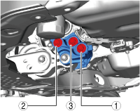
9. Tighten the No.3 engine mount installation bolts and nuts in the order shown in the figure.
ac9uuw00006372
|
Tightening torque
|
No. |
Tightening torque |
|---|---|
|
1
|
76—95 N·m {7.8—9.6 kgf·m, 57—70 ft·lbf}
|
|
2
|
82—95 N·m {8.4—9.6 kgf·m, 61—70 ft·lbf}
|
|
3
|
49—65 N·m {5.0—6.6 kgf·m, 37—47 ft·lbf}
|
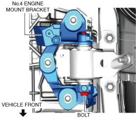
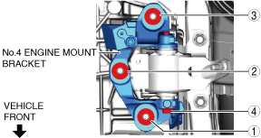
10. Tighten the No.4 engine mount bracket installation bolt and nuts in the order shown in the figure.
ac9uuw00006373
|
Tightening torque
|
No. |
Tightening torque |
|---|---|
|
1, 2, 3
|
92—116 N·m {9.4—11 kgf·m, 68—85 ft·lbf}
|
|
4
|
81—99 N·m {8.3—10 kgf·m, 60—73 ft·lbf}
|
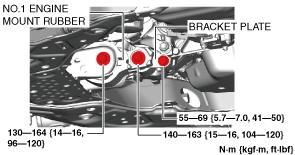
11. Tighten the No.1 engine mount rubber installation bolts.
2WD
ac9uuw00006374
|
4WD
ac9uuw00006375
|
12. Install the clips shown in the figure. (with i-ELOOP)
ac9wzw00004458
|
13. Install the wiring harness bracket shown in the figure. (with i-ELOOP)
ac9wzw00003840
|
14. Connect the generator terminal B cable. (with i-ELOOP) (See GENERATOR REMOVAL/INSTALLATION [WITH i-ELOOP (SKYACTIV-G 2.5T)].)
15. Install the service plug. (with i-ELOOP) (See SERVICE PLUG DISCONNECTION/CONNECTION [i-ELOOP].)
16. Connect the clip shown in the figure.
ac9uuw00006363
|
17. Install the ground cable shown in the figure.
ac9uuw00006376
|
18. Return the cooler hose that was set aside to its original position and tighten the nut.
ac9wzw00005520
|
19. Install the PCM component using the following procedure:
ac9uuw00006378
|
ac9uuw00006379
|
ac9uuw00007432
|
20. Install the ground cable shown in the figure.
ac9uuw00006381
|