1. : Mazda SST number
2. : Global SST number
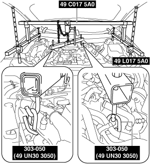
1: 49 UN30 3050
2: 303–050
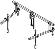
Engine lifting brackets
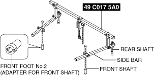
1: 49 C017 5A0
2: –
Engine support set
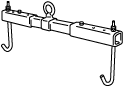
1: 49 L017 5A0
2: –
Support hanger
AUTOMATIC TRANSAXLE REMOVAL/INSTALLATION [GW6AX-EL]
id0517i21172i4
Special Service Tool (SST)
|
1. : Mazda SST number
2. : Global SST number
|
|||||
|
1: 49 UN30 3050
2: 303–050
Engine lifting brackets
|
|
1: 49 C017 5A0
2: –
Engine support set
|
|
1: 49 L017 5A0
2: –
Support hanger
|
|
Replacement Part
|
washer
Quantity: 1
Location of use: plug
|
Removal
1. Disconnect the negative battery terminal. (See NEGATIVE BATTERY TERMINAL DISCONNECTION/CONNECTION.)
2. Remove the air cleaner, air hose and fresh air duct as a single unit. (See INTAKE-AIR SYSTEM REMOVAL/INSTALLATION [SKYACTIV-G 2.5T].)
3. Remove the battery and battery tray. (See BATTERY REMOVAL/INSTALLATION.)
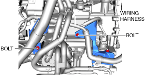
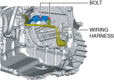
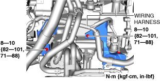
4. Remove the wiring harness with the bracket from the transaxle.
ac9uuw00008926
|
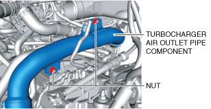
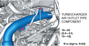
5. Remove the turbocharger air outlet pipe component installation nuts.
ac9uuw00008927
|
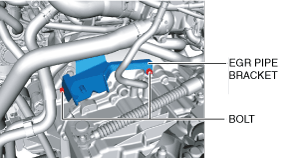
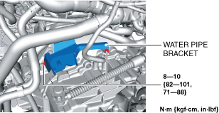
6. Remove the water pipe bracket installation bolts.
ac9uuw00008928
|
7. Remove the front splash shield. (See FRONT SPLASH SHIELD REMOVAL/INSTALLATION.)
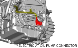
8. Disconnect the electric AT oil pump connector. (With electric AT oil pump)
ac9wzw00004554
|
9. Remove the wiring harness with the bracket from the transaxle. (With electric AT oil pump)
ac9wzw00004560
|
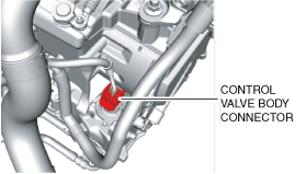
10. Disconnect the control valve body connector.
ac9uuw00008957
|
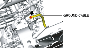
11. Disconnect the ground cable.
ac9uuw00008930
|
12. Disconnect the selector cable from the transaxle. (See AUTOMATIC TRANSAXLE SHIFT MECHANISM REMOVAL/INSTALLATION.)
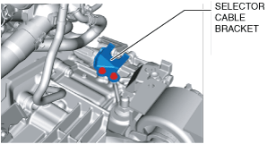
13. Remove the selector cable bracket.
ac9uuw00008959
|
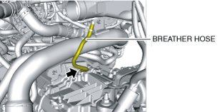
14. Disconnect the breather hose from the transaxle.
ac9uuw00008932
|
15. Remove the joint cover. (See STEERING WHEEL AND COLUMN REMOVAL/INSTALLATION.)
16. Disconnect the intermediate shaft from the steering gear and linkage. (See STEERING WHEEL AND COLUMN REMOVAL/INSTALLATION.)
17. Remove the front tires. (See WHEEL AND TIRE REMOVAL/INSTALLATION.)
18. Remove the front under cover No.2. (See FRONT UNDER COVER No.2 REMOVAL/INSTALLATION.)
19. Remove the front under cover No.1. (See FRONT UNDER COVER No.1 REMOVAL/INSTALLATION.)
20. Drain the engine coolant. (See ENGINE COOLANT REPLACEMENT [SKYACTIV-G 2.5T].)
21. Drain the ATF. (See AUTOMATIC TRANSAXLE FLUID (ATF) REPLACEMENT [GW6A-EL, GW6AX-EL].)
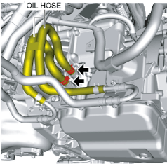
22. Disconnect the oil hose from the transaxle. (With oil cooler No.2) (See OIL COOLER REMOVAL/INSTALLATION [GW6A-EL, GW6AX-EL].)
ac9wzw00004915
|
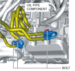
23. Remove the bolts shown in the figure and set the oil pipe component in a place which does not interfere with the servicing. (With oil cooler No.2) (See OIL COOLER REMOVAL/INSTALLATION [GW6A-EL, GW6AX-EL].)
ac9wzw00004916
|
24. Disconnect the oil cooler from the transaxle with the hose connected. (Except automatic transaxle replacement) (See OIL COOLER REMOVAL/INSTALLATION [GW6A-EL, GW6AX-EL].)
25. Disconnect the water hose from the oil cooler. (Automatic transaxle replacement) (See OIL COOLER REMOVAL/INSTALLATION [GW6A-EL, GW6AX-EL].)
26. Remove the starter. (See STARTER REMOVAL/INSTALLATION [SKYACTIV-G 2.5T].)
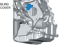
27. Remove the blind cover.
ac9uuw00008963
|
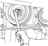
28. Hold the crankshaft pulley to prevent drive plate from rotating.
ac4ccw00002081
|
29. Remove the torque converter nuts from the starter installation hole.
ac9uuw00008964
|
30. Disconnect the front ABS wheel-speed sensors from the steering knuckles. (See FRONT ABS WHEEL-SPEED SENSOR REMOVAL/INSTALLATION.)
31. Disconnect the clips securing the brake hose from the front shock absorbers. (See FRONT BRAKE (DISC) REMOVAL/INSTALLATION.)
32. Disconnect the tie-rod end ball joints from the steering knuckles. (See STEERING GEAR AND LINKAGE REMOVAL/INSTALLATION.)
33. Disconnect the front lower arms from the steering knuckles. (See FRONT LOWER ARM REMOVAL/INSTALLATION.)
34. Disconnect the front stabilizer control links from the front stabilizer. (See FRONT STABILIZER REMOVAL.)
35. Disconnect the front drive shaft (LH) from the transaxle. (See FRONT DRIVE SHAFT REMOVAL/INSTALLATION.)
36. Remove the front drive shaft (RH) from the transfer. (See FRONT DRIVE SHAFT REMOVAL/INSTALLATION.)
37. Remove the propeller shaft. (See PROPELLER SHAFT REMOVAL/INSTALLATION.)
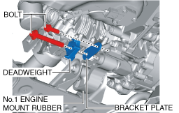
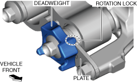
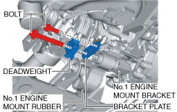
38. Remove the bracket plate and deadweight. (See ENGINE MOUNT DISASSEMBLY/ASSEMBLY [SKYACTIV-G 2.5T].)
ac9uuw00008965
|
39. Remove the front crossmember component and No.1 engine mount rubber as a single unit. (See FRONT CROSSMEMBER REMOVAL/INSTALLATION.)
40. Remove the transfer. (See TRANSFER REMOVAL/INSTALLATION [GW6AX-EL].)
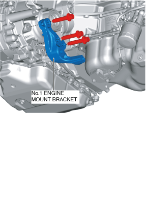
41. Remove the No.1 engine mounting bracket.
ac9uuw00008966
|
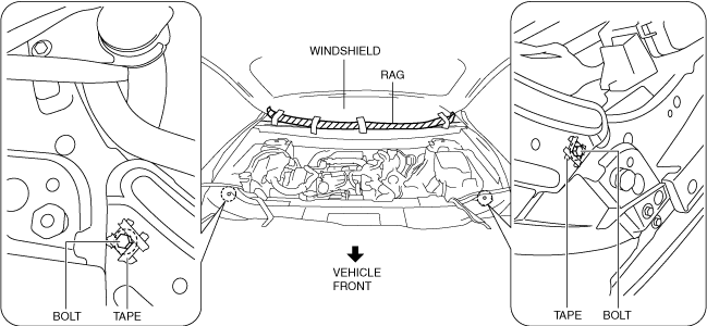
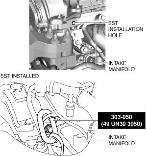
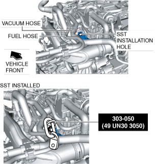
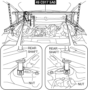
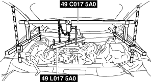
42. Install the SST using the following procedures.
ac5wzw00004357
|
ac9uuw00008967
|
ac9uuw00006492
|
ac9uuw00009472
|
Engine front side
ac9uuw00006493
|
Engine rear side
ac9uuw00008969
|
ac9uuw00008970
|
ac9uuw00008971
|
ac9uuw00008972
|
ac9uuw00008973
|
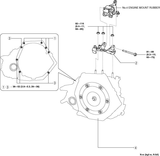
43. Remove in the order shown in the figure.
ac9uuw00009226
|
|
1
|
Transaxle mounting bolts (upper side)
|
|
2
|
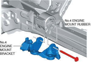
No.4 engine mount bracket
|
|
3
|
Transaxle mounting bolts (lower side)
|
|
4
|
Transaxle
|
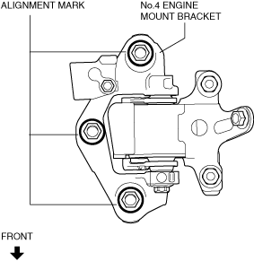
No.4 engine mount bracket removal note
1. Place alignment marks on the locations shown in the figure so that they can be assembled to the same positions as before removal.
ac9uuw00009227
|
2. Remove the No.4 engine mount bracket.
Transaxle mounting bolt removal note
1. Adjust the SST and lean the engine toward the transaxle.
ac9uuw00008972
|
2. Support the transaxle on a jack.
ac5wzw00004369
|
3. Remove the transaxle mounting bolts (lower side).
4. Remove the transaxle.
Installation
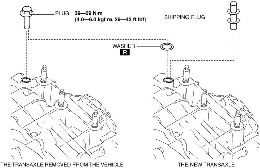
1. If the transaxle is replaced with a new one, perform the following procedure.
ac9uuw00011693
|
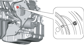
2. Verify that the torque converter stud bolts are inserted into the drive plate bolt holes from the starter installation hole.
ac9uuw00008974
|
3. Install the transaxle mounting bolts.
ac5wzw00004371
|
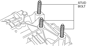
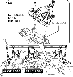
4. Tighten the stud bolts for the transaxle.
ac5wzw00004372
|
5. Install the No.4 engine mount bracket to No.4 engine mount rubber, and temporarily tighten the installation bolt.
ac9uuw00008975
|
6. Pull up the transaxle using the SSTs, pass the transaxle stud bolts through the No.4 engine mount bracket, and temporarily tighten the No.4 engine mount installation nuts.
ac9uuw00008976
|
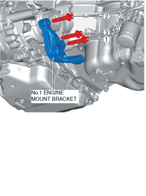
7. Install the No.1 engine mount bracket and tighten the bolts in the order shown in the figure.
ac9uuw00009228
|
8. Install the transfer. (See TRANSFER REMOVAL/INSTALLATION [GW6AX-EL].)
9. Install the front crossmember component and No.1 engine mount rubber as a single unit. (See FRONT CROSSMEMBER REMOVAL/INSTALLATION.)
10. Temporarily install the No.1 engine mount rubber, deadweight and bracket plate.
ac8wzw00002540
|
ac9uuw00008977
|
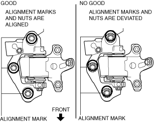
11. Align the positions of the No.4 engine mount bracket installation nuts with the No.4 engine mount bracket.
ac5wzw00004377
|
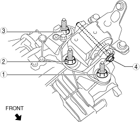
12. Tighten the No.4 engine mount bracket installation nuts and bolt in the order shown in the figure.
ac5wzw00004378
|
|
No. |
Tightening torque |
|---|---|
|
1, 2, 3
|
92—116 N·m {9.4—11 kgf·m, 69—85 ft·lbf}
|
|
4
|
81—99 N·m {8.3—10 kgf·m, 60—73 ft·lbf}
|
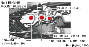
13. Tighten the No.1 engine mount rubber and bracket plate installation bolts.
ac9wzw00005002
|
14. Install the propeller shaft. (See PROPELLER SHAFT REMOVAL/INSTALLATION.)
15. Remove the SSTs.
16. Install the cowl panel. (See COWL PANEL REMOVAL/INSTALLATION.)
17. Install the cowl grille. (See COWL GRILLE REMOVAL/INSTALLATION.)
18. Install the windshield wiper arm and blade. (See WINDSHIELD WIPER ARM AND BLADE REMOVAL/INSTALLATION.)
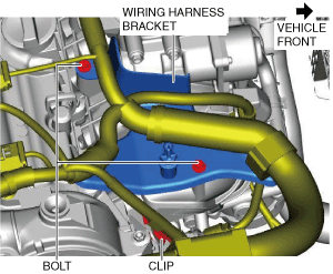
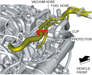
19. Connect the clip shown in the figure to the protector.
ac9uuw00009472
|
20. Install the bolts and clip shown in the figure.
ac9uuw00006526
|
21. Fix the crankshaft pulley to lock the torque converter against rotation.
ac4ccw00002081
|
22. Tighten the torque converter installation nut.
ac9uuw00008964
|
23. Install the blind cover.
ac9uuw00008963
|
24. Install the starter. (See STARTER REMOVAL/INSTALLATION [SKYACTIV-G 2.5T].)
25. Install the front drive shaft (RH) to the transfer. (See FRONT DRIVE SHAFT REMOVAL/INSTALLATION.)
26. Connect the front drive shaft (LH) to the transaxle. (See FRONT DRIVE SHAFT REMOVAL/INSTALLATION.)
27. Connect the front stabilizer control links to the front stabilizer. (See FRONT STABILIZER INSTALLATION.)
28. Connect the front lower arms to the steering knuckles. (See FRONT LOWER ARM REMOVAL/INSTALLATION)
29. Connect the tie-rod end ball joints to the steering knuckles. (See STEERING GEAR AND LINKAGE REMOVAL/INSTALLATION.)
30. Connect the clips securing the brake hose to the front shock absorbers. (See FRONT BRAKE (DISC) REMOVAL/INSTALLATION.)
31. Connect the front ABS wheel-speed sensors to the steering knuckles. (See FRONT ABS WHEEL-SPEED SENSOR REMOVAL/INSTALLATION.)
32. Connect the water hose to the oil cooler. (Automatic transaxle replacement) (See OIL COOLER REMOVAL/INSTALLATION [GW6A-EL, GW6AX-EL].)
33. Connect the oil cooler to the transaxle with the hose connected. (Except automatic transaxle replacement) (See OIL COOLER REMOVAL/INSTALLATION [GW6A-EL, GW6AX-EL].)
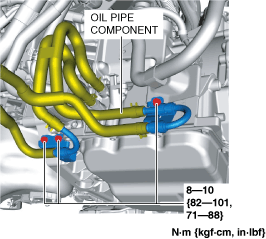
34. Connect the oil pipe component. (With oil cooler No.2) (See OIL COOLER REMOVAL/INSTALLATION [GW6A-EL, GW6AX-EL].)
ac9wzw00004917
|
35. Connect the oil hose to the transaxle. (With oil cooler No.2) (See OIL COOLER REMOVAL/INSTALLATION [GW6A-EL, GW6AX-EL].)
ac9wzw00004915
|
36. Install the front under cover No.1. (See FRONT UNDER COVER No.1 REMOVAL/INSTALLATION.)
37. Install the front under cover No.2. (See FRONT UNDER COVER No.2 REMOVAL/INSTALLATION.)
38. Install the front tires. (See WHEEL AND TIRE REMOVAL/INSTALLATION.)
39. Connect the intermediate shaft to the steering gear and linkage. (See STEERING WHEEL AND COLUMN REMOVAL/INSTALLATION.)
40. Install the joint cover. (See STEERING WHEEL AND COLUMN REMOVAL/INSTALLATION.)
41. Connect the breather hose to the transaxle.
ac9uuw00008932
|
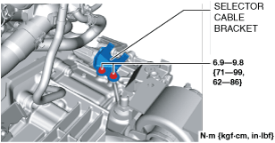
42. Install the selector cable bracket.
ac9uuw00008979
|
43. Connect the selector cable to the transaxle. (See AUTOMATIC TRANSAXLE SHIFT MECHANISM REMOVAL/INSTALLATION.)
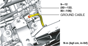
44. Connect the ground cable as shown in the figure.
ac9uuw00008980
|
45. Connect the control valve body connector.
ac9uuw00008957
|
46. Install the wiring harness with the bracket to the transaxle. (With electric AT oil pump)
ac9wzw00004561
|
47. Connect the electric AT oil pump connector. (With electric AT oil pump)
ac9wzw00004554
|
48. Install the front splash shield. (See FRONT SPLASH SHIELD REMOVAL/INSTALLATION.)
49. Install the water pipe bracket installation bolts.
ac9uuw00008981
|
50. Install the turbocharger air outlet pipe component installation nuts.
ac9uuw00008982
|
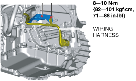
51. Install the wiring harness with the bracket to the transaxle.
ac9uuw00008953
|
52. Install the battery and battery tray. (See BATTERY REMOVAL/INSTALLATION.)
53. Install the air cleaner, air hose and fresh air duct as a single unit. (See INTAKE-AIR SYSTEM REMOVAL/INSTALLATION [SKYACTIV-G 2.5T].)
54. Connect the negative battery terminal. (See NEGATIVE BATTERY TERMINAL DISCONNECTION/CONNECTION.)
55. Refill the engine coolant. (See ENGINE COOLANT REPLACEMENT [SKYACTIV-G 2.5T].)
56. Add the ATF. (See AUTOMATIC TRANSAXLE FLUID (ATF) REPLACEMENT [GW6A-EL, GW6AX-EL].)
57. Perform the “TCM configuration” (Automatic Transaxle Replacement). (See TCM CONFIGURATION [GW6A-EL, GW6AX-EL].)
58. Perform the “Initial Learning” (automatic transaxle replacement). (See INITIAL LEARNING [GW6A-EL, GW6AX-EL].)
59. Perform the “Mechanical System Test”. (See MECHANICAL SYSTEM TEST [GW6A-EL, GW6AX-EL].)