1. : Mazda SST number
2. : Global SST number
1: 49 UN30 3050
2: 303–050
Engine lifting bracket
1: 49 L017 5A0
2: –
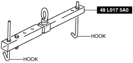
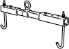
Support hanger
—
ENGINE DISASSEMBLY/ASSEMBLY [SKYACTIV-G 2.5T]
id0110q8800500
Special Service Tool (SST)
|
1. : Mazda SST number
2. : Global SST number
|
||||
|
1: 49 UN30 3050
2: 303–050
Engine lifting bracket
|
|
1: 49 L017 5A0
2: –
Support hanger
|
|
—
|
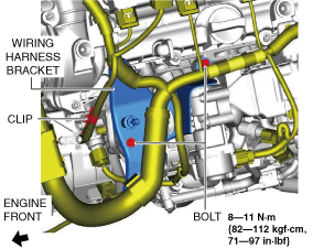
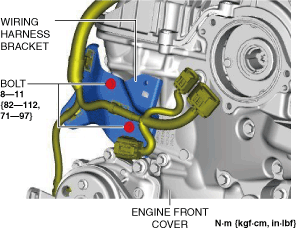
1. To enable to install the SST, remove the bolts and clip shown in the figure and set the wiring harness bracket aside.
ac9uuw00006388
|
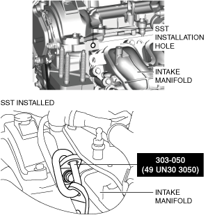
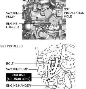
2. Install the SST using part number 99794 1025 or an M10 x 1.25, length 25 mm {0.98 in} bolt as shown in the figure.
Engine front side
ac9uuw00007417
|
Engine rear side
ac9uuw00007418
|
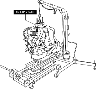
3. Engage the hooks of the SST (49 L017 5A0) to the SST (49 UN30 3050).
am6zzw00011714
|
4. To ensure the safety of the work (control engine and transaxle sway), set a hoist as shown in the figure.
ac9uuw00006391
|
5. Remove the WU-TWC. (See EXHAUST SYSTEM REMOVAL/INSTALLATION [SKYACTIV-G 2.5T].)
6. Remove the dynamic pressure turbo. (See DYNAMIC PRESSURE TURBO REMOVAL/INSTALLATION [SKYACTIV-G 2.5T].)
7. Remove the oil cooler. (See OIL COOLER REMOVAL/INSTALLATION [SKYACTIV-G 2.5T].)
8. Remove the exhaust manifold. (See EXHAUST SYSTEM REMOVAL/INSTALLATION [SKYACTIV-G 2.5T].)
9. Remove the starter. (See STARTER REMOVAL/INSTALLATION [SKYACTIV-G 2.5T].)
10. Fix the drive plate using the crankshaft pulley lock bolt.
11. Remove the torque converter installation nut from the starter installation hole. (See AUTOMATIC TRANSAXLE REMOVAL/INSTALLATION [GW6A-EL] (2WD).) (See AUTOMATIC TRANSAXLE REMOVAL/INSTALLATION [GW6AX-EL] (4WD).)
12. Disconnect the engine and transaxle, and lower only the engine from the engine lifter. (See AUTOMATIC TRANSAXLE REMOVAL/INSTALLATION [GW6A-EL] (2WD).) (See AUTOMATIC TRANSAXLE REMOVAL/INSTALLATION [GW6AX-EL] (4WD).)
13. Remove the generator. (See GENERATOR REMOVAL/INSTALLATION [WITHOUT i-ELOOP (SKYACTIV-G 2.5T)].) (See GENERATOR REMOVAL/INSTALLATION [WITH i-ELOOP (SKYACTIV-G 2.5T)].)
14. Remove the EGR cooler and EGR valve component. (See EGR COOLER REMOVAL/INSTALLATION [SKYACTIV-G 2.5T].) (See EGR VALVE REMOVAL/INSTALLATION [SKYACTIV-G 2.5T].)
15. Remove the thermostat. (See THERMOSTAT REMOVAL/INSTALLATION [SKYACTIV-G 2.5T].)
16. Remove the water pipe component and oil cooler pipe component. (See CYLINDER HEAD GASKET REPLACEMENT [SKYACTIV-G 2.5T].)
17. Remove the flange and water inlet pipe. (See CYLINDER HEAD GASKET REPLACEMENT [SKYACTIV-G 2.5T].)
18. Remove the intake-air system. (See INTAKE-AIR SYSTEM REMOVAL/INSTALLATION [SKYACTIV-G 2.5T].)
19. Remove the oil separator. (See POSITIVE CRANKCASE VENTILATION (PCV) VALVE REMOVAL/INSTALLATION [SKYACTIV-G 2.5T].)
20. Remove the knock sensor (KS). (See KNOCK SENSOR (KS) REMOVAL/INSTALLATION [SKYACTIV-G 2.5T].)
21. Remove the fuel injectors. (See FUEL INJECTOR REMOVAL/INSTALLATION [SKYACTIV-G 2.5T].)
22. Remove the camshaft position (CMP) sensor. (See CAMSHAFT POSITION (CMP) SENSOR REMOVAL/INSTALLATION [SKYACTIV-G 2.5T].)
23. Remove the vacuum pump. (See VACUUM PUMP REMOVAL/INSTALLATION.)
24. Remove the high pressure fuel pump and rear housing. (See HIGH PRESSURE FUEL PUMP REMOVAL/INSTALLATION [SKYACTIV-G 2.5T].)
25. Remove the electric variable valve timing motor/driver. (See ELECTRIC VARIABLE VALVE TIMING MOTOR/DRIVER REMOVAL/INSTALLATION [SKYACTIV-G 2.5T].)
26. Remove the drive belt auto tensioner. (See DRIVE BELT AUTO TENSIONER REMOVAL/INSTALLATION [SKYACTIV-G 2.5T].)
27. Remove the oil filter. (See OIL FILTER REPLACEMENT [SKYACTIV-G 2.5T].)
28. Remove the engine oil solenoid valve. (See ENGINE OIL SOLENOID VALVE REMOVAL/INSTALLATION [SKYACTIV-G 2.5T].)
29. Remove the crankshaft position (CKP) sensor. (See CRANKSHAFT POSITION (CKP) SENSOR REMOVAL/INSTALLATION [SKYACTIV-G 2.5T].)
30. Remove the dipstick.
31. Remove the ignition coil/ion sensors. (See IGNITION COIL/ION SENSOR REMOVAL/INSTALLATION [SKYACTIV-G 2.5T].)
32. Remove the purge bracket component, vacuum pipe component and air pipe component. (See TIMING CHAIN REMOVAL/INSTALLATION [SKYACTIV-G 2.5T].)
33. Remove the wiring harness bracket shown in the figure.
ac9uuw00006393
|
34. Remove the emission harness.
35. Remove the water pump drive belt. (See DRIVE BELT REMOVAL/INSTALLATION [SKYACTIV-G 2.5T].)
36. Remove the water pump component. (See WATER PUMP REMOVAL/INSTALLATION [SKYACTIV-G 2.5T].)
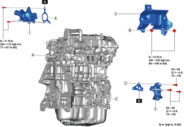
37. Remove in the order indicated in the table.
38. Assemble in the reverse order of disassembly.
ac9wzw00003835
|
|
1
|
Water outlet component
|
|
2
|
Insulator
|
|
3
|
Oil filter body
|
Oil Filter Body Installation Note
1. After tightening the three bolts, tighten the first tightened bolt to the specified tightening torque again.